Decametric Receiver Construction 


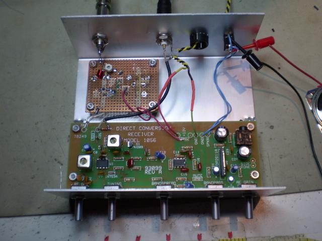
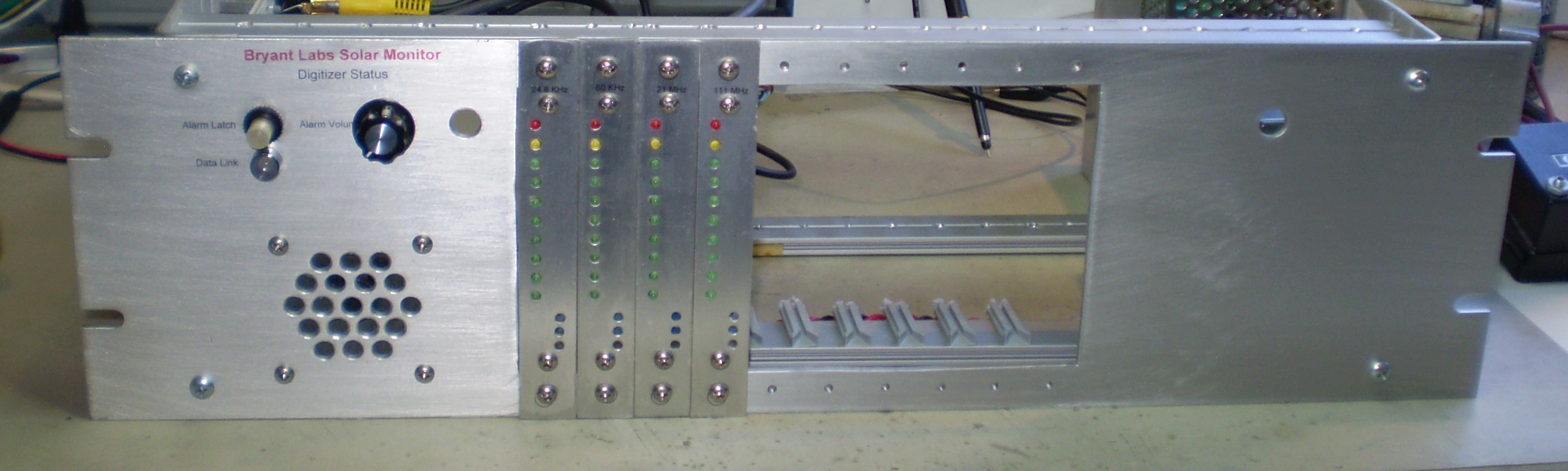
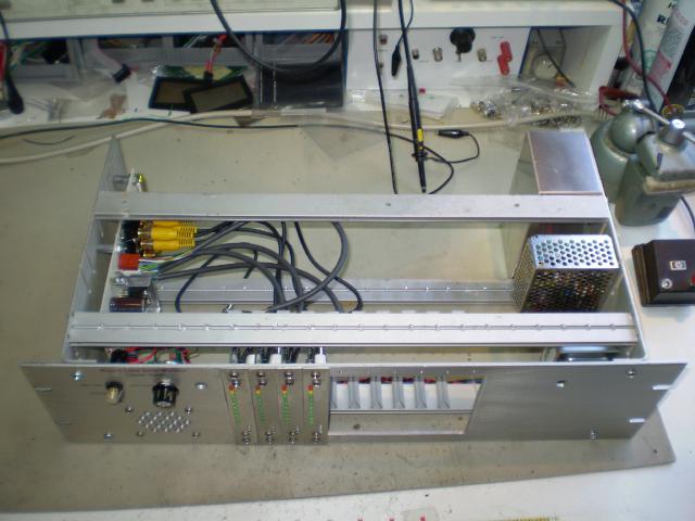
Here's the inside of the receiver for monitoring the 20.1MHz region ala Radio Jove. Since I always want to do things the hard way, I didn't buy a Radio Jove receiver. This is a Ten-Tec Model 1056 Direct Conversion receiver kit that I built and modified for solar radio astronomy. The folks over at Fringe Dwellers have some information about using this receiver, and I thought it would be a good one to try. While the Radio Jove Receiver is easier to build for a complete newbie, the TT-1056 is much cheaper. It does need a few modifications.

The '1056 comes with parts to cover the 15 Meter Ham band, but that is just a little higher than the 20-21MHz we want to cover. Fringe Dwellers suggest replacing C1 and C3 with 56pF instead of the supplied 47pF parts in the kit. I think you might want to go a little higher. I found that 47pF + 10pF in parallel just gets to 20.1MHz at the absolute low end of the dial on my kit.

I also changed the Local Oscillator output from the 1Mohm series resistor to a simple emitter follower buffer using an MMBT5179 transistor stuck to the bottom of the board. It works great to drive my frequency counter without affecting the tuning. You can see the added coax from the board to the rear panel in the picture above.

Finally, I added a 20 MHz pre-amp and pre-selector to improve the front end performance. Here's a closeup of the pre-amp board:


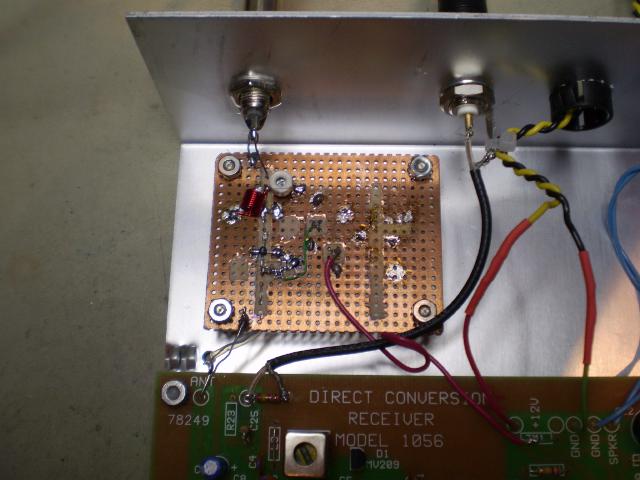
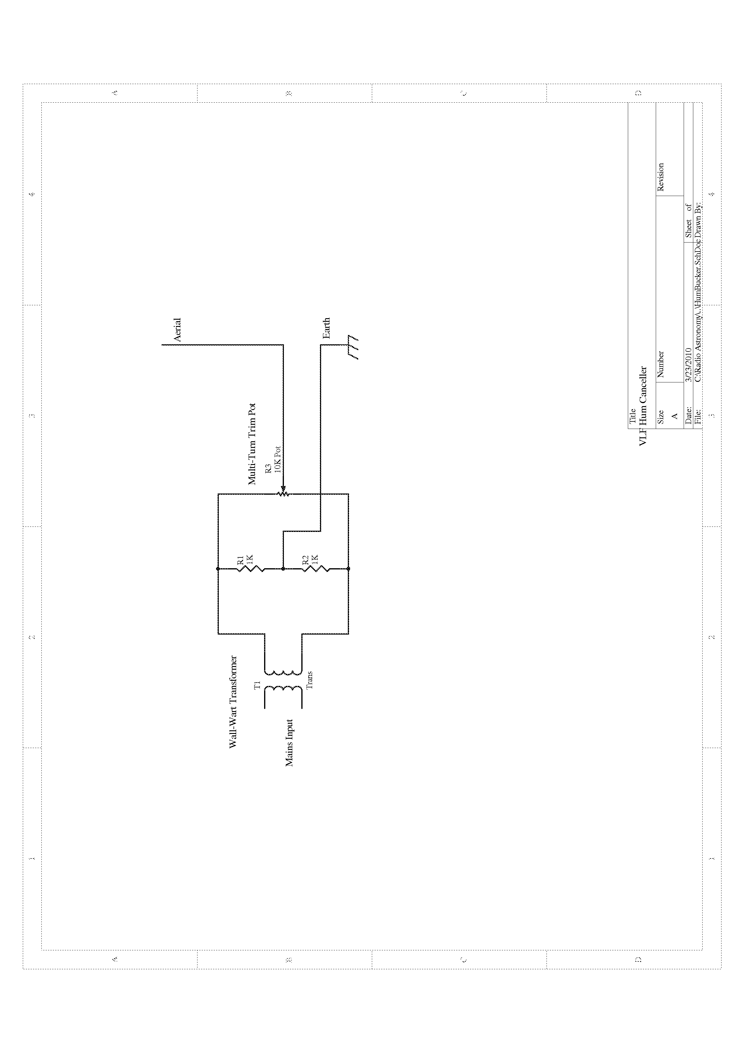
And here's a link to the schematic of it.

Amplification is provided by a Mini-Circuits ERA-3 Monolithic Amplifier. These little building blocks are very handy for things like this. A few years back I picked up one of their Designer Kits which had ten each of the ERA-1, ERA-2, and ERA-3 amps for about $50. That's less than $2 each.

The front end filter is lifted from the Radio Jove receiver schematic. I didn't have any 0.47uH inductors on-hand, so I wound one after designing it using this nice tool at Missouri University of Science and Technology. It takes a few iterations to find a combination of turns and diameter that gets the right inductance, but that's inductors for you. There are lots of ways to calculate the inductance of a structure, but no tools to tell you how to bend the wire to get a specific inductance. Just remember that the radius in the calculation is to the center of the wire. You need to subtract off the wire radius to figure out the radius of the form. I have one of those big drill bit kits from Harbor Freight, so I have lots of form sizes to choose from.

With everything put together, the receiver can detect a signal down to about -130dBm at the antenna input. Now I just need to build a suitable antenna for it.

Cheers,

Keith
[ add comment ] ( 18 views ) [ 0 trackbacks ] permalink ( 3 / 1974 )
VLF Hum Canceller Schematic 


The schematic in my last post looked crappy, so here's a better one. It's a jpeg, so right click on the image to bring up the larger full resolution version.

Cheers,

Keith
[ add comment ] ( 21 views ) [ 0 trackbacks ] permalink ( 3 / 2010 )
Hum Cancellation for VLF Receivers 

I mentioned my trick for mitigating mains noise pickup in VLF antenna/amplifier setups at the SARA Western Conference over the weekend, and many people asked for more details. Here are a couple of pictures and a quick schematic.

The basic idea is to cancel out some of the local mains electric field right at the antenna by "transmitting" a small field that is out of phase. I have only tried this trick with electric field antennas. It might be interesting to try it with an extra winding around a loop too. First, locate a wall-wart that can be opened up easily. I found this one in my junk box, and it was held together with screws instead of glue. The label is gone, but I think this one was rated at 5VDC. The current doesn't matter since we will be drawing almost no power from it. DC outputs are preferred, since they will have some extra room we can use.


Once you have gotten it open, remove the rectifier/capacitor circuit. Be careful with the transformer secondary leads, that's the part you really need. You might want to use the original output cable, or change to a connector like I did. Figure out how you will access the trim-pot. I found a neat trimmer with a panel mount bushing in a bin at HSC. I haven't found these in a catalog, but Mouser carries a Vishay/Spectrol adapter that holds a standard trimmer on a panel.

If you lucked out, the transformer has a center tap that can be tied to earth. If not, you either need to add a couple of resistors as shown in this schematic, or you need a switch to choose the polarity of the cancelling signal.


With a center tap (real or virtual) the trim pot allows us to adjust the cancellation signal from max in-phase through zero to max out of phase.

To set it up, run some wire from the output of the device up near your antenna. My antenna is a piece of 3/4" Copper water pipe, about 8 feet long ( about 19mm by 2.4 meters). I tie-wrapped a couple of nylon standoffs to the side of the pipe and attached a section of 14AWG bare copper wire to them. You will need to experiment with this, so start with about a cubit. That's the length of your forearm, a very handy unit if you ask me. Connect one wire from the hum-bucker to it and the other to a nearby earth ground.

Now, look at the output of your antenna amplifier on an oscilloscope, and play with the adjustment on the hum-bucker to get minimum mains frequency noise. You won't be able to cancel it completely, but you should be able to reduce it considerably.

That's about it. There are plenty of areas for experimentation. For instance, it should be possible to adjust the phase with an RC network of some kind, or you might make the virtual ground network adjustable too.

Have Fun!

Keith
[ add comment ] ( 28 views ) [ 0 trackbacks ] permalink ( 3 / 1928 )
SARA Western Conference 

I just got around to uploading my pictures from the SARA Western Conference held at Stanford University last weekend. I had a great time, and I'm sure everyone who attended did too. Bill and Melinda Lord did a fantastic job organizing the meeting, and a special thanks goes to Phillip and Deborah Scherrer who were our hosts at Stanford.


This is the famous Stanford Dish from the front side. After spending most of the conference indoors, it was nice to get out and have a look about. Our first stop was the big dish to get a detailed inside tour. The dish is 150 feet in diameter - you get some sense of scale from the cars in front of it. The whole works including the control room rotates around on four rail car wheels riding on a circular track.

It was a beautiful day, and we could see Mount Hamilton, Mount Diablo, and NASA Ames research center:


I think the rectangular structure in the picture is the inlet to the huge wind tunnel at Ames. In the foreground, the interesting shaped white building is the Wilcox Solar Observatory which we toured after visiting Stanford Radio Club facility. All of these facilities are within a huge park-like area open to hikers. We felt bad riding in cars while they trudged up the hills!

That's it for now, I'll comment on some of the presentations next time.

Cheers,

Keith

[ add comment ] ( 59 views ) [ 0 trackbacks ] permalink related link ( 3 / 1890 )
Solar Monitor Chassis Progress 


I've completed most of the mechanical work on the Solar Monitor Chassis. This picture shows the front panel with the core module interface on the left and four completed bar graph modules installed. The upper left control is a lighted push-button switch with an integral yellow LED. It lights if one of the modules lit the red LED. Pushing the button clears that latch. To the right of that is the beeper volume. Below the push-button switch is an indicator that is green if Radio Sky Pipe is actively scanning channels. It goes red if something stops.

The layout isn't aesthetically ideal because I recycled the panel and had to work around holes that already existed. The good news is that the array of holes for the speaker were already done and I had a speaker that fit them.


This shows some of the guts of the thing. On the left you can see the connections to from the modules to the core module. The right side is all power supply. The box in the rear holds the power entry module and acts as a junction box for the AC. In front of that is the 5V/3A supply for the LEDs and digital stuff. Just visible in the front corner is the 18VCT transformer that supplies the OP-Amps and A/D converter.

I fired it up with Sky Pipe and it works great so far. Now I need to get the front end radios working.

Cheers,

KeithP
[ add comment ] ( 12 views ) [ 0 trackbacks ] permalink ( 3 / 1837 )

<<First <Back | 1 | 2 | 3 | 4 | 5 | 6 | Next> Last>>