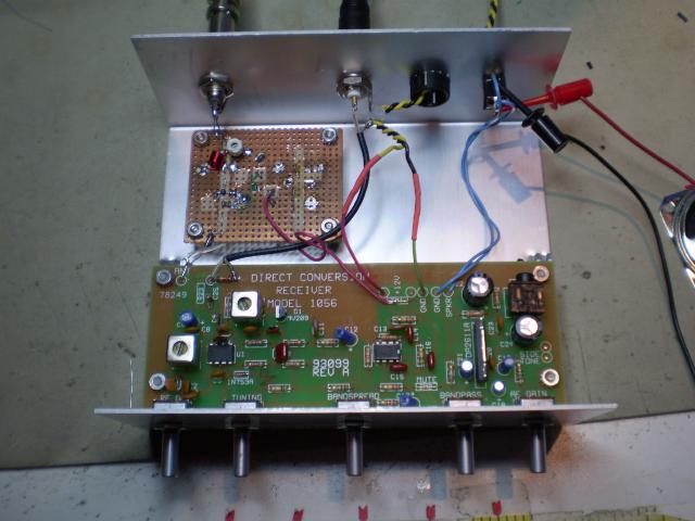
Here's the inside of the receiver for monitoring the 20.1MHz region ala Radio Jove. Since I always want to do things the hard way, I didn't buy a Radio Jove receiver. This is a Ten-Tec Model 1056 Direct Conversion receiver kit that I built and modified for solar radio astronomy. The folks over at Fringe Dwellers have some information about using this receiver, and I thought it would be a good one to try. While the Radio Jove Receiver is easier to build for a complete newbie, the TT-1056 is much cheaper. It does need a few modifications.
The '1056 comes with parts to cover the 15 Meter Ham band, but that is just a little higher than the 20-21MHz we want to cover. Fringe Dwellers suggest replacing C1 and C3 with 56pF instead of the supplied 47pF parts in the kit. I think you might want to go a little higher. I found that 47pF + 10pF in parallel just gets to 20.1MHz at the absolute low end of the dial on my kit.
I also changed the Local Oscillator output from the 1Mohm series resistor to a simple emitter follower buffer using an MMBT5179 transistor stuck to the bottom of the board. It works great to drive my frequency counter without affecting the tuning. You can see the added coax from the board to the rear panel in the picture above.
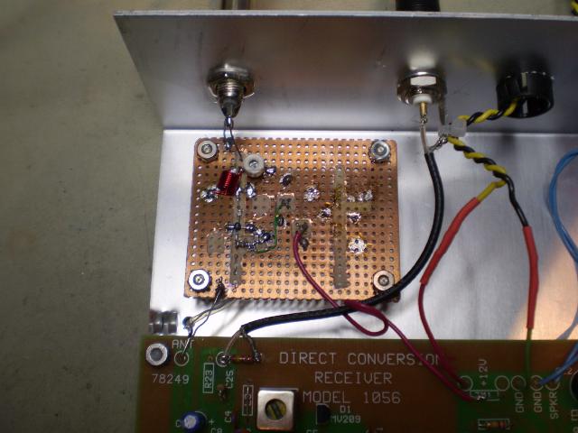
Finally, I added a 20 MHz pre-amp and pre-selector to improve the front end performance. Here's a closeup of the pre-amp board:

And here's a link to the schematic of it.
Amplification is provided by a Mini-Circuits ERA-3 Monolithic Amplifier. These little building blocks are very handy for things like this. A few years back I picked up one of their Designer Kits which had ten each of the ERA-1, ERA-2, and ERA-3 amps for about $50. That's less than $2 each.
The front end filter is lifted from the Radio Jove receiver schematic. I didn't have any 0.47uH inductors on-hand, so I wound one after designing it using this nice tool at Missouri University of Science and Technology. It takes a few iterations to find a combination of turns and diameter that gets the right inductance, but that's inductors for you. There are lots of ways to calculate the inductance of a structure, but no tools to tell you how to bend the wire to get a specific inductance. Just remember that the radius in the calculation is to the center of the wire. You need to subtract off the wire radius to figure out the radius of the form. I have one of those big drill bit kits from Harbor Freight, so I have lots of form sizes to choose from.
With everything put together, the receiver can detect a signal down to about -130dBm at the antenna input. Now I just need to build a suitable antenna for it.
Cheers,
Keith


 Calendar


