Musings of an Amateur Scientist
http://bryantlabs.net/Blog/index.php
Hacked Toaster Oven for SMT soldering
http://bryantlabs.net/Blog/index.php?entry=entry100725-105449
I picked up a cheap toaster oven to do reflow soldering as described in many places on the web. It worked marginally well. There were two problems. 1) The highest temp setting was right at the solder melt temperature threshold, and 2) the temperature swings were awful since it is a simple bi-metallic strip thermostat.
A while back, I picked up a pair of Omega CN7000 temperature controllers at the Valley of the Moon Amateur Radio Club hamfest in Sonoma. One had a bad display, and the other was missing the output relay. I swapped parts and ended up with one good controller. Time to start hacking...
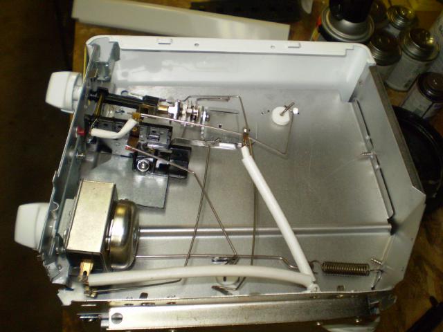
Here I have taken the end cover off the toaster. You can see the thermostat and control switches at the top left, and the timer with bell at the bottom. After figuring out how it was connected, I removed all of the controls in preparation for adding my own.
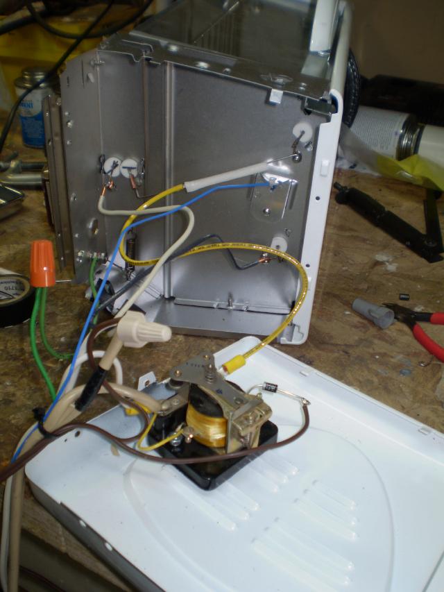
The toaster needs about 11 or 12 amps with all of the elements turned on, and the relay in the CN7000 is only rated at 9 amps. Luckily I had a 20 Amp rated relay with a 110VDC coil in my junk box. I mounted this to the inside of the end cover and started wiring it all together.
The toaster has two pairs of elements, one on top, and one on bottom. Each pair is connected in series at the far end, and the pairs are connected in parallel at this end. The center wires of the elements get really hot, so the original used welded connections. I left some of the original wire intact on each element, bent it into a small circle, and used SS screws to bolt the connections together.
The main power cord comes in and the hot side goes to one of the contacts on the relay. The neutral goes to the big wire nut, and the ground wire goes to the chassis of the toaster. One side of the series/parallel heaters goes to neutral, and the other to the other side of the relay. Two bits of zip cord go out to the CN7000. One provides power to it, and the other goes to the output contacts to switch power to the big relay coil.
The diode next to the relay coil converts the 110AC to 110DC. This picture doesn't show the 10uF, 200V capacitor also required. I know, running 110AC through a diode doesn't give you 110DC. But, it's close enough to operate the relay coil very nicely. In fact, I could use a smaller capacitor since short "off" times from the controller don't open the main relay.
I buttoned it all up and gave it a spin. My procedure is to set the controller for 150C and let the oven warm up while I prep the board. I put solder paste on the pads to be soldered (using a toothpick), and put the parts in place. The paste does a decent job of holding them while I move the board to the oven and put it on the rack.
Close the door and wait about 3 minutes to bring everything up to temperature. Then, I set the controller for about 210C and watch the temperature climb. When it gets to about 195 and the solder starts to melt, I wait 30 more seconds and then pull the plug. Wait another 30 seconds, and then open the door to let it cool. After a couple of minutes I pull it out of the oven completely and let it come down to room temperature. Voila! soldered SMT parts.
It's a little noisy as the relay clacks on and off, and I need to figure out a clean way to attach the controller to the oven, but for now it works great.
Cheers,
Keith]]>I need a bigger telescope
http://bryantlabs.net/Blog/index.php?entry=entry100721-224452
2010 Golden State Star Party (GSSP) up in Adin, California. Adin is a great little town, and the local people are super nice. GSSP is held on a few acres of Albaugh's Frosty Acres Ranch. The organizers do a great job of turning an empty cow pasture into a self contained astronomy encampment for four nights. The skies are incredibly dark. The site is on a bit of a rise in the middle of the "Big Valley", so you can see house lights some miles away. Once you realize how far away they are an just look up, you can practically read by the light of the Milky Way.
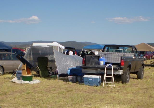
Here's a shot of my camp, complete with Orion 8" dob.
It's nice and cozy. The Aluminet provides much needed shade, especially when trying to sleep in after a long night of observing.
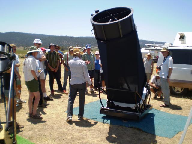
The problem is that there are some seriously big telescopes there: .
This one is a custom made 30" telescope. I can't really call it a dob, since money appeared to be no object in its construction. It is an alt-az mount, completely motorized and computerized for go-to operation. I left feeling quite inadequate in the aperture department. I wonder how much I can get away with spending on a bigger telescope before the spouse complains....
I'll be headed to Yosemite with the Sonoma County Astronomical Association in about a week. More great camping with telescopes!
Cheers,
Keith]]>Monitoring WWVB
http://bryantlabs.net/Blog/index.php?entry=entry100610-195121
I can think of a few ways to do this that would be easy to implement:
1) Pure analog setup with a ramp and a sample/hold circuit 2) Frequency counter with a & b inputs to measure the time. 3) Microprocessor to measure the time difference.
Since I have a suitable counter, maybe I'll set up to watch the time difference over a few days to see how it looks before deciding on a final approach.
Thoughts anyone?
Cheers,
Keith]]>Maker Faire
http://bryantlabs.net/Blog/index.php?entry=entry100524-204400
Maker Faire in San Mateo. I've been a big fan of Make magazine since it debuted, and I have been to all of the Bay Area Maker Faires. This year was really great. A mind-bending experience as always. Plenty of Steampunk, model rockets, trebuchets, mad science, tesla coils, robots, you name it. I highly recommend attending.
The other nerdy thing I did was to go to Sturgeon's mill, which is a steam powered saw mill in western Sonoma County. The mill has been on this spot since the 1920s. When it was shut down in about 1963, Wade Sturgeon, one of the original partners, continued living on the site. He had the foresight to keep the rain off the old mill, and to go out once a week with his oil can to keep everything lubed and moving. I wish more people could think ahead that way. Recently a group including Wade's family got together and brought it all back to life. When you stand on the deck as they saw logs, you can feel the pulse of the steam engine and hear the exhaust note change as the saw blade bites into the log. IT'S ALIVE!!!
Cheers,
Keith]]>Decametric Receiver Mods
http://bryantlabs.net/Blog/index.php?entry=entry100502-190357
The guys at Fringe Dwellers recommend adding a switch to allow you to bypass the bandpass filter stage altogether. This goes a little too far the other way for my suburban location. The Radio Jove receiver has a multi-pole filter with a 3.5 KHz bandwidth. I decided to follow their lead. I put a simple RC filter in place and so far it seems to be working well.
Here's how it is hooked up. Remove the "Mute" jumper and put an SPDT switch across it with the common to the right end. Across R12 (3.3K), put a series combination of a 1K resistor with a 0.047uF cap. The resistor goes to the right, the other end of R12 is ground. The node where the resistor joins the cap connects to the other end of the bypass switch. Voila, a simple RC filter.
Now to record data for a couple of days and see how my results compare to others.
Cheers,
Keith]]>Astronomy Day 2010 at the RFO
http://bryantlabs.net/Blog/index.php?entry=entry100424-133324
Robert Ferguson Observatory. We are getting a good crowd for Solar observing which will last until 4:00 PM. Then after a break for a meeting and dinner, we'll be back to show the night sky. I brought my Orion 8" dob, several others will be here with small scopes, and all of the large scopes in the observatory will be operating. We also have not 1, but 4 lecturers who will be giving a variety of talks starting at 8:00 PM.
Although there are no sunspots today, the sun appears to be active in the decametric radio spectrum. Dean has picked up several noise bursts on the Radio Jove receiver.
Wherever you are, there should be some club doing public astronomy today. If not, at least go out and look at the moon and Venus tonight just after sunset.
Dark Skies!
Keith]]>Radio-SkyPipe Data on-line
http://bryantlabs.net/Blog/index.php?entry=entry100421-205012
here. The prominent red track is from the 24.8KHz Gyrator II receiver monitoring NLK at Jim Creek, Wa. The flat orange track near the bottom is from the 20.1MHz receiver. I'm still working on that one. I hope to have something on the other channel soon too.
I've also taken info from some of my posts here and started to create some "permanent" pages on my solar monitor project. This Linkwill take you there. So far, it just covers the system mainframe and bar graph modules. Over the next few weeks I'll add pages for each receiver/sensor too.
Cheers,
Keith]]>Orion XT8 Classic - New Base
http://bryantlabs.net/Blog/index.php?entry=entry100418-130436
Orion XT8 Classic Dobsonian Telescope for years and I love it. Last year at the Golden State Star Party we were "treated" to a thunderstorm the first night. I managed to stay pretty dry, but the base of my telescope got wet. Particle Board does not like to get wet.
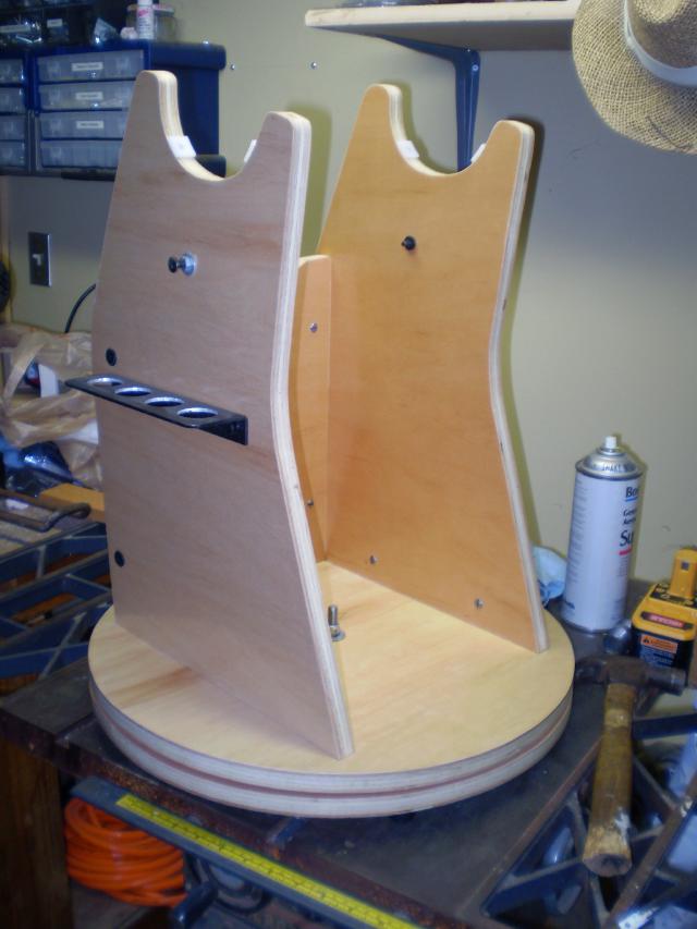
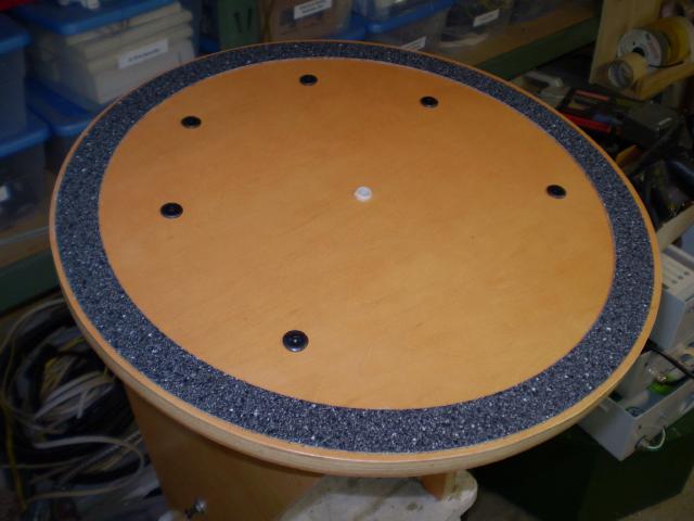
About a week later, it was starting to come apart. Luckily, I had a half sheet of 3/4" hardwood plywood left over from a kitchen remodel we did a couple of years ago. I took the original base apart and used the pieces as templates to cut new ones from the plywood. I reused as much of the original hardware as possible. I changed the connections between the pieces to some steel knock-down furniture fasteners. These are the kind where the screw that holds two boards together threads into the side a special pin that goes in a second hole drilled at right angles to the screw hole. They work really well and don't rely on screw threads biting into the edge of the plywood. Here's a picture of the complete base:
One problem I had was that the azimuth movement was sticky. It was just teflon pads riding on the multiple coats of polyurethane. The original was high pressure laminate on the friction surface. Telescope Builder folklore held that "Ebony Star" laminate in combination with the teflon pads gave the best results. Luckily, Scope Stuff sells pre-cut rings of the stuff complete with a set of pads. The prices look a little high at first, but they do include shipping, which can be expensive on an awkward part like this.
Laminate is generally installed with contact cement. My quandary was how to apply the cement to the base without making a mess. Here's how I did it.
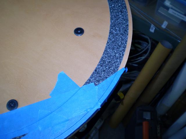
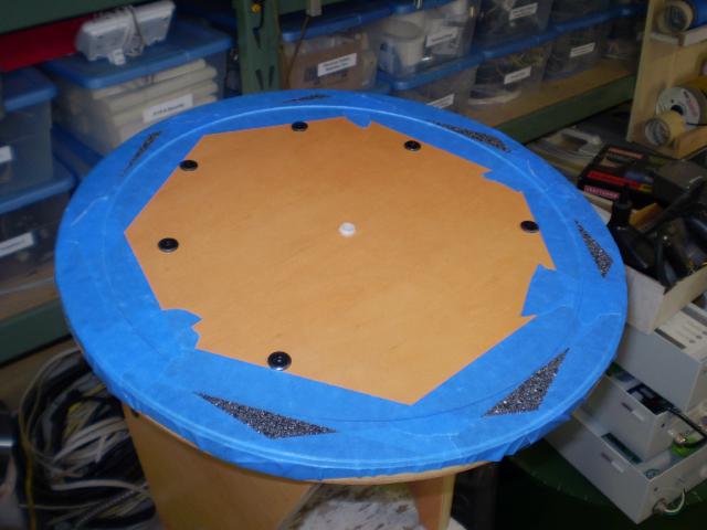
First, I centered the ring on the bottom of the rocker box with a couple of pieces of masking tape. Then, I started covering the laminate with tape, making sure to leave plenty of tape off the sides, and not worrying about completely covering the laminate itself.
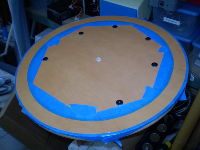
When I had it all taped, I made a registration mark on the tape and then took an X-Acto knife to carefully cut around both edges of the laminate leaving a perfectly masked ring.
The contact cement goes on with a little brush in the bottle, so I didn't need to mask any more like I would with a spray adhesive. I put two coats on the base because of the shiny surface, and one coat on the back side of the laminate. When they were ready to go (Read the instructions) I put a bunch of cable ties laying flat across the glued area on the base to keep the ring from sticking all at once. When I had the ring lined up nicely, I pulled the cable ties out one-by-one and pressed the ring into place.
I also replaced the original teflon pads on the ground board with the new ones that came with the laminate ring. Now my telescope swings around nicely. Just the right combination of drag and ease of movement.
I'm planning to give it a really good workout this coming weekend (24-Apr-2010) for Astronomy Day at the Robert Ferguson Observatory.
Clear Dark Skies to All!
Keith ]]>Decametric Antenna Part 2
http://bryantlabs.net/Blog/index.php?entry=entry100416-115113
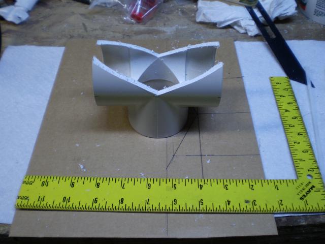
These started out as standard 2" PVC "T" fittings which I cut to fit the ridge of the garage roof. You can see the template I used to mark the key points on the fittings before cutting. I went a little steep on the angle so that they would tend to rest on the ends and not rock in the middle. I just clamped them in a woodworking vise and cut with a hacksaw.
I also pre-cut the ropes to make the installation go faster since the forecast was for some showers randomly through the day.
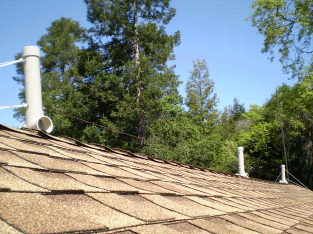
Here's the antenna installed on the roof. You can just about make out the wires in the photo. The ropes at each end are tied to eye bolts that are screwed into the trim boards on the gable ends of the roof. The eye bolts are screwed in at a slight angle so the ropes won't rub on the edge of the roof. I'll probably need to adjust the ropes once everything settles in.
The finished antenna seems to be working great. I have the 20.1 MHz receiver hooked to it and collecting data on Radio Sky-Pipe. I need to work through the image save/FTP upload process so I can get some recordings posted on the site.
Then I'll be working on finalizing the 111 MHz receiver and modifying my WWVB receiver to give me signal strength measurements.
Cheers,
Keith]]>Decametric Antenna, Part 1
http://bryantlabs.net/Blog/index.php?entry=entry100407-200409
Radio Jove antenna is a dual dipole. I actually considered trying to fit one of these on the top of my garage, but I figured my wife and neighbors would not be pleased... Also, it is fairly narrow band, and won't work very far from it's design frequency of 20.1MHz. I want to be able to explore more of the band without adding more antennas.
After some searching on the web, I came across the T2FD, short for Tilted, Terminated, Folded Dipole. The pdf at this link has a good article called "A Total Flux HF Radiometer" by Colin Clements that discusses the T2FD, and is where I first heard about it. There's also a good article here.
Anyone with an FM receiver at home probably has seen a folded dipole. They are often supplied as the basic antenna, made of 300 ohm twin-lead. I've built these myself when I needed a quick and dirty antenna for 100MHz-ish frequencies.
Folded dipoles in general are fairly broad-band, and terminated ones are even more so. The basic idea is to insert a terminating resistor in the center of the top wire directly opposite the feed point. The resistor is supposed to be just a little more than the feed point impedance. How much more is subject to some debate, but generally it's agreed that with a 300 ohm feed impedance, the terminator should be about 390 ohms. I'm using 75 Ohm coax with a homemade 1:4 balun at the feed point.
The "Tilted" part of the description comes from putting one end up in a tree to improve the directionality of the antenna along the ground. I want the antenna to look up, so I will just string mine horizontally.
The roof of my garage is about 24 feet long, and the ridge is oriented close to North/South. I want to keep the antenna ends in a few feet from the edges to allow for guying. I chose an overall length of 6 meters. This should result in a minimum frequency of 16.666MHz (100/L Meters) and a maximum about 4-5 times that. Based on the literature, the wires should be spaced at 0.18 meters (3/F MHz), or just over 7".
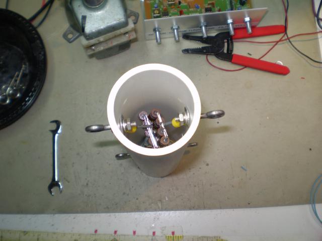
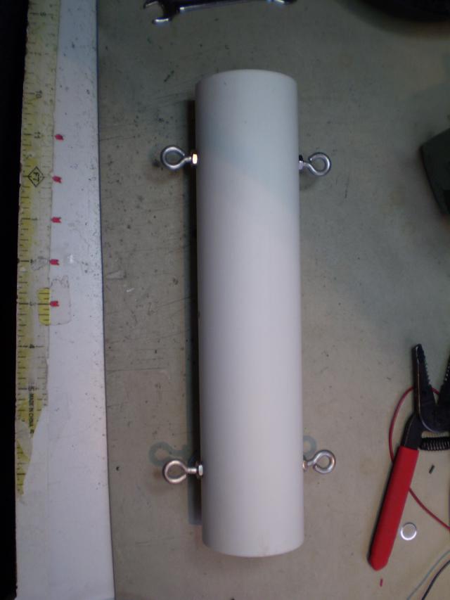
The center of the antenna will be made of 2" PVC pipe to hold the terminator and balun. This is the bottom end with the balun and "F" connector
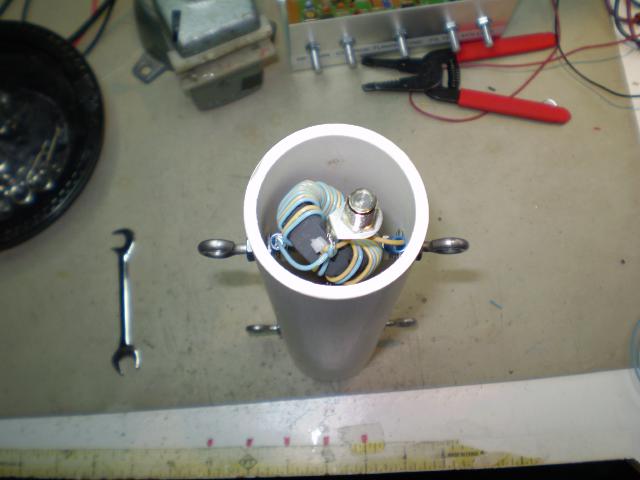
This is the top end with the terminator installed.
And this one is a side view showing the eye-bolts where the wires will attach. The end spreaders will look the same as this, but with nothing inside. Each one will have wire looping through the two loops on one side, and guy ropes on the other. The top will get a matching PVC Cap, and the bottom of each will sit in a "T" fitting that's been cut to fit the ridge of the roof.
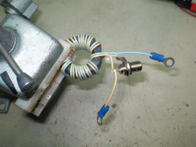
Here's a closeup of the balun in my vice. It's 16 turns bifilar wound 24AWG wire with insulation. It's wound on an Amidon FT-140-67 Core. Lots of super-glue holds it all together.
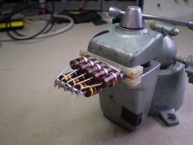
And here's a closeup of the terminator. I have a junkbox full of 2W resistors, none of them 390 Ohms. I have lots of 680 Ohm resistors and 100 ohm resistors. The bottom layer in the stack consists of 8 x 680 ohm resistor in series/parallel to give 340 ohms. The top layer is a set of 5 x 100 Ohm resistors in parallel. Those are in series with the bottom layer. But, that doesn't add up to 390, does it? Well, the 680's were on the high side of their tolerance, and resulted in about 370 ohms. I added more 100 Ohm resistors in parallel to compensate.
Both terminator and balun are clearly bigger than they need to be for just receiving. It cost me nothing extra to do this and it leaves open the possibility of using this as a low power transmitting antenna in the future.
Next up I'll have some pictures of the actual installation.
 .
.