Now that I have a working receiver, I need a good antenna. The classic Radio Jove antenna is a dual dipole. I actually considered trying to fit one of these on the top of my garage, but I figured my wife and neighbors would not be pleased... Also, it is fairly narrow band, and won't work very far from it's design frequency of 20.1MHz. I want to be able to explore more of the band without adding more antennas.
After some searching on the web, I came across the T2FD, short for Tilted, Terminated, Folded Dipole. The pdf at this link has a good article called "A Total Flux HF Radiometer" by Colin Clements that discusses the T2FD, and is where I first heard about it. There's also a good article here.
Anyone with an FM receiver at home probably has seen a folded dipole. They are often supplied as the basic antenna, made of 300 ohm twin-lead. I've built these myself when I needed a quick and dirty antenna for 100MHz-ish frequencies.
Folded dipoles in general are fairly broad-band, and terminated ones are even more so. The basic idea is to insert a terminating resistor in the center of the top wire directly opposite the feed point. The resistor is supposed to be just a little more than the feed point impedance. How much more is subject to some debate, but generally it's agreed that with a 300 ohm feed impedance, the terminator should be about 390 ohms. I'm using 75 Ohm coax with a homemade 1:4 balun at the feed point.
The "Tilted" part of the description comes from putting one end up in a tree to improve the directionality of the antenna along the ground. I want the antenna to look up, so I will just string mine horizontally.
The roof of my garage is about 24 feet long, and the ridge is oriented close to North/South. I want to keep the antenna ends in a few feet from the edges to allow for guying. I chose an overall length of 6 meters. This should result in a minimum frequency of 16.666MHz (100/L Meters) and a maximum about 4-5 times that. Based on the literature, the wires should be spaced at 0.18 meters (3/F MHz), or just over 7".
The center of the antenna will be made of 2" PVC pipe to hold the terminator and balun. This is the bottom end with the balun and "F" connector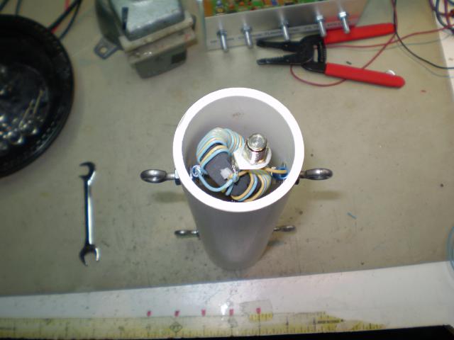
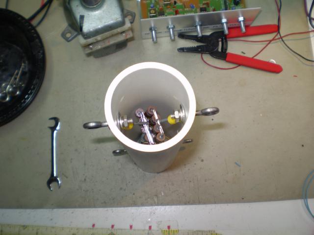
This is the top end with the terminator installed.
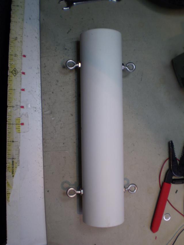
And this one is a side view showing the eye-bolts where the wires will attach. The end spreaders will look the same as this, but with nothing inside. Each one will have wire looping through the two loops on one side, and guy ropes on the other. The top will get a matching PVC Cap, and the bottom of each will sit in a "T" fitting that's been cut to fit the ridge of the roof.
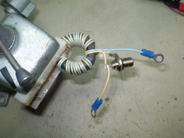
Here's a closeup of the balun in my vice. It's 16 turns bifilar wound 24AWG wire with insulation. It's wound on an Amidon FT-140-67 Core. Lots of super-glue holds it all together.
And here's a closeup of the terminator. I have a junkbox full of 2W resistors, none of them 390 Ohms. I have lots of 680 Ohm resistors and 100 ohm resistors. The bottom layer in the stack consists of 8 x 680 ohm resistor in series/parallel to give 340 ohms. The top layer is a set of 5 x 100 Ohm resistors in parallel. Those are in series with the bottom layer. But, that doesn't add up to 390, does it? Well, the 680's were on the high side of their tolerance, and resulted in about 370 ohms. I added more 100 Ohm resistors in parallel to compensate.
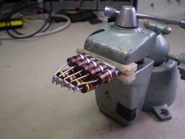
Both terminator and balun are clearly bigger than they need to be for just receiving. It cost me nothing extra to do this and it leaves open the possibility of using this as a low power transmitting antenna in the future.
Next up I'll have some pictures of the actual installation.
Cheers,
Keith
[ add comment ] ( 82 views ) [ 0 trackbacks ] permalink After some searching on the web, I came across the T2FD, short for Tilted, Terminated, Folded Dipole. The pdf at this link has a good article called "A Total Flux HF Radiometer" by Colin Clements that discusses the T2FD, and is where I first heard about it. There's also a good article here.
Anyone with an FM receiver at home probably has seen a folded dipole. They are often supplied as the basic antenna, made of 300 ohm twin-lead. I've built these myself when I needed a quick and dirty antenna for 100MHz-ish frequencies.
Folded dipoles in general are fairly broad-band, and terminated ones are even more so. The basic idea is to insert a terminating resistor in the center of the top wire directly opposite the feed point. The resistor is supposed to be just a little more than the feed point impedance. How much more is subject to some debate, but generally it's agreed that with a 300 ohm feed impedance, the terminator should be about 390 ohms. I'm using 75 Ohm coax with a homemade 1:4 balun at the feed point.
The "Tilted" part of the description comes from putting one end up in a tree to improve the directionality of the antenna along the ground. I want the antenna to look up, so I will just string mine horizontally.
The roof of my garage is about 24 feet long, and the ridge is oriented close to North/South. I want to keep the antenna ends in a few feet from the edges to allow for guying. I chose an overall length of 6 meters. This should result in a minimum frequency of 16.666MHz (100/L Meters) and a maximum about 4-5 times that. Based on the literature, the wires should be spaced at 0.18 meters (3/F MHz), or just over 7".
The center of the antenna will be made of 2" PVC pipe to hold the terminator and balun. This is the bottom end with the balun and "F" connector
This is the top end with the terminator installed.
And this one is a side view showing the eye-bolts where the wires will attach. The end spreaders will look the same as this, but with nothing inside. Each one will have wire looping through the two loops on one side, and guy ropes on the other. The top will get a matching PVC Cap, and the bottom of each will sit in a "T" fitting that's been cut to fit the ridge of the roof.
Here's a closeup of the balun in my vice. It's 16 turns bifilar wound 24AWG wire with insulation. It's wound on an Amidon FT-140-67 Core. Lots of super-glue holds it all together.
And here's a closeup of the terminator. I have a junkbox full of 2W resistors, none of them 390 Ohms. I have lots of 680 Ohm resistors and 100 ohm resistors. The bottom layer in the stack consists of 8 x 680 ohm resistor in series/parallel to give 340 ohms. The top layer is a set of 5 x 100 Ohm resistors in parallel. Those are in series with the bottom layer. But, that doesn't add up to 390, does it? Well, the 680's were on the high side of their tolerance, and resulted in about 370 ohms. I added more 100 Ohm resistors in parallel to compensate.
Both terminator and balun are clearly bigger than they need to be for just receiving. It cost me nothing extra to do this and it leaves open the possibility of using this as a low power transmitting antenna in the future.
Next up I'll have some pictures of the actual installation.
Cheers,
Keith

 ( 3 / 2766 )
 Calendar


