Bryant Labs
Seismology - Vertical Seismometer Design
![]()
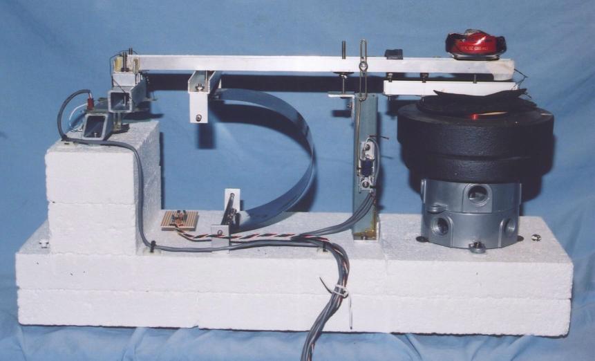
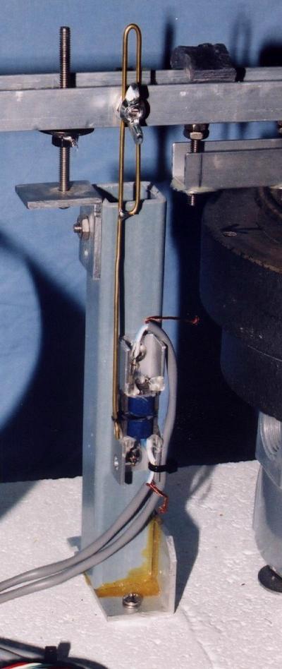
Below are a photo and a simplified drawing of the STM-8 vertical seismometer as I built it. If you are lloking for the schematics and theory of operation, go to the Seismometer Electronics page.
The base consists of concrete paving stones fastened together with "Liquid Nails" type adhesive formulated for use on concrete. There are two layers of pavers, each layer made up of one 8 inch square paver and one 8 by 16 inch paver. The joints are staggered for maximum strength.
At the left end, I stacked up two concrete (not classic fired clay) bricks and attached them with the same adhesive. After letting the glue set for over a week with the clamps on, I coated the whole works with a good brand of primer-sealer paint. This keeps the worst of the moisture out of the concrete and makes it look prettier.
To attach components to the concrete, I epoxied steel "T" nuts into holes drilled into the concrete. If you have never used this kind of hardware, it looks like a threaded standoff where one end is flared out to a flat disk. In some kinds of "T" nuts, the flange is plain, but they make types that have prongs for pounding into wood, or holes to attach them with little brads or screws. I like the kind with the little holes, since the epoxy oozes through them to make a better bond. Be sure to clean everything very well, and use a screw as a handle to make it easier to work with. Since these holes are reasonably small, almost any drill equipped with a masonry bit will work.
The Boom is a simple piece of aluminum "U" channel. It should be as light as possible while still maintaining some rigidity. It is pivoted at the left end with a crossed flexure type of hinge. See the detail farther down the page
The Mass is a Coke can which has been cut down to about 1 inch and filled with Lead. I embedded a 6-32 bolt in it before pouring in the molten lead.
The Spring is a 12 inch Drywall Taping knife made of spring steel. I cut off the handle with a Dremel tool. It is attached with a fairly complex pivot scheme intended to avoid any stick-slip friction noise. Sean mentions this many times, but it bears repeating: Be very careful when handling the spring when it is under tension. It can really fly if it slips out of your hands!
I've gotten many questions about how to connect the ends of the spring to the base and the boom. To help answer those questions, I've created this Spring Detail page. Be Patient. To get the kind of detail that everyone wanted, the pictures are large and may take a while to load.
The sensor is the same VRDT type as described on Sean's pages. It was a little tricky to build and keep everything lined up, but it has been very reliable in use. The basic idea is that there are two coils mounted on "E" cores mounted face to face with a small gap between them. They are attached to the base. A pointer made of brass rod, with an attached bit of core material is attached to the boom and positioned so that with the boom in equilibrium, the pointer is centered in the gap. Turning this into a usable signal is up to the electronics.
The final piece of this mechanical puzzle is the feedback mechanism. The voice coil and magnet from an old Altec woofer are mounted with the voice coil attached to the boom and the magnet mounted to the base. Getting them aligned takes a lot of patience! The electronics takes the position sensor signal and filters it and then drives the voice coil to lengthen the period of the instrument. The natural period is about 1 second with the power off. When the feedback is turned on, it goes out to about 60 seconds.
The little piece of perfboard to the left of the leaf spring is a temperature sensor (TMP-02). In the future, I want to use it to compensate for baseline drift over temperature.
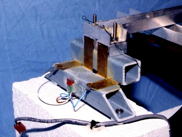
The Hinge is an interesting piece in itself. From the photo and the drawing below, you can get some idea of how it works. It consists of two pieces of square tubing (I used 1" square fiberglass) that are connected by four thin strips of brass shim stock. The square tubes are aligned corner to corner. The strips of brass are epoxied to the tubes. One reason I used fiberglass tubing is that the brass strips end up insulated from each other, so I can use them to run the feedback signal to the voice coil out on the boom.
The reason for using this type of hinge is that it has no sliding parts which would contribute noise to the system. It does take some force to bend the brass strips, but the limiting factor in this seismometer is not sensitivity, but noise.
Here's a close-up of the sensor. It is mounted to a piece of the same fiberglass tubing used in the hinge. The "core" of the sensor consists of the two coils mounted in the small piece of aluminum U channel. They are modified transformers, where the core laminations have been re-arranged to make an "E" shape. The two cores are then epoxied to the channel with the open sides facing each other with a gap of about 1/8 inch. The brass rod is attached to the boom with a way to adjust it's position. On the lower end of the rod is a small piece of leftover transformer lamination material. It is positioned so that it is centered between the coils when the seismometer is at rest.
The L bracket at the top of the sensor post holds a screw which passes through a large hole in the boom and acts as a safety limit stop. There are nuts and washers above and below the boom. In normal operation, the boom doesn't touch the screw or the nuts, but when moving the unit, or in a really big quake, this helps keep the seismometer from being damaged.
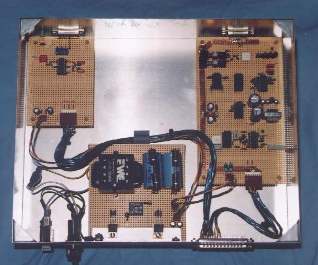
Finally, here's a picture of the electronics for this seismometer. For the schematics and Theory of Operations, go to the Seismometer Electronics page. In the bottom of the picture (the back of the box), we have the power supply. I used linear regulators, heatsinked to the side wall of the box via a piece of aluminum angle. In the lower right is the output connector which goes back to one of Larry Cochrane's A/D Boards. In the upper left is a board which amplifies the signals from a 3 Axis strong motion sensor. Finally, in the upper right, is the support board for the Vertical Seismometer. Here again you can see my use of copper foil tape for a good ground.
![]()
Last Revised: 12-October-2003