Bryant Labs
Thermo-Electric Cooler Controller
![]()
NOTE: Click on thumbnail to see a larger image
|
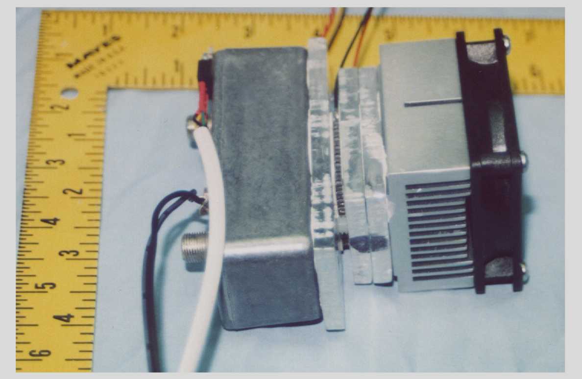
This image shows the stack-up of the LNA, TEC, FAN, and the aluminum plates I used to hold everything together. Starting from the left, we have the LNA itself. It is a stock kit from Downeast Microwave. The black wires are for the LNA power, and the white wire connects to the temperature sensor. Next is an aluminum plate which acts as a cold plate. The thin object next in sthe stack is the TEC module itself. Next there are two more aluminum plates which adapt the TEC to the heat sink. On top of the heat sink is the fan. |
|
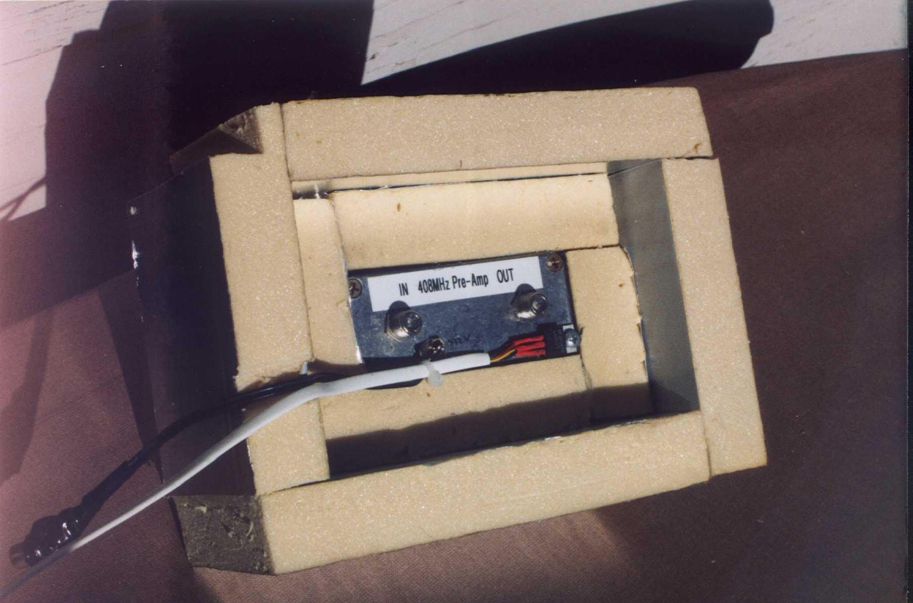
This image shows the front of the assembly inside it's wrap of insulation. You can also see more clearly the LM35DT temperature sensor. I mounted it by removing one of the LNA cover screws and replacing it with a pan-head screw of the same size. The insulation consists of pieces of 1" foam insulation board cut to size and hot glued together. |
|
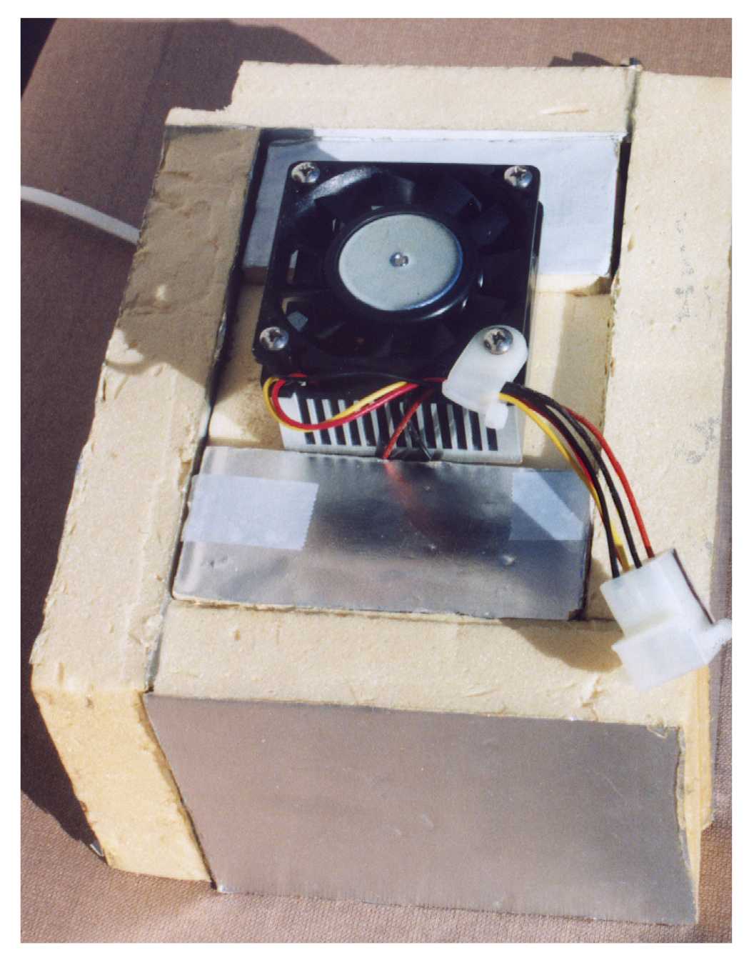
This image shows the rear of the assembly inside the insulation wrapper. The small pieces of foam around the heat sink are not glued - they are just held by friction. This allows me to remove the assembly from the foam without major destruction. |
|
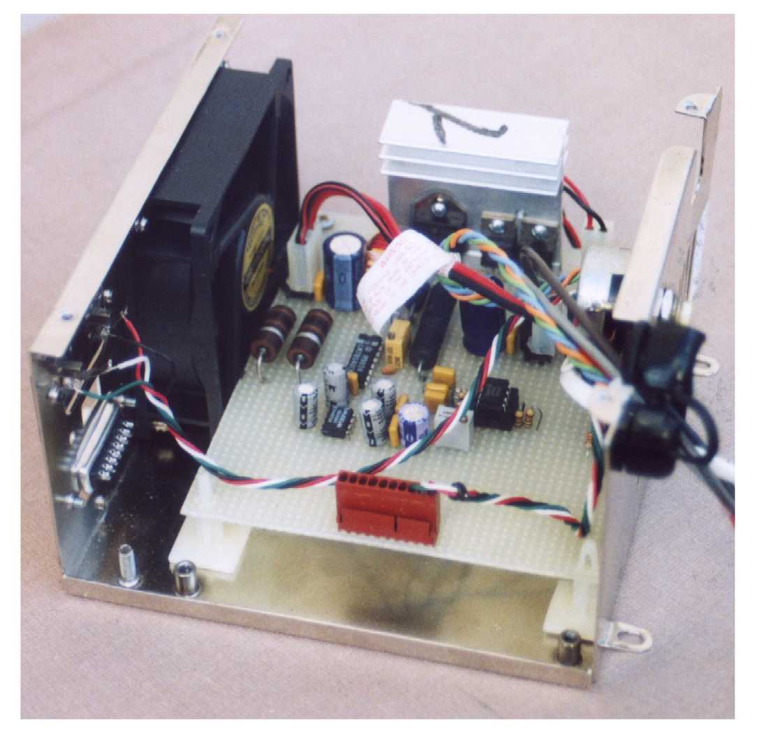
This photo shows the inside of the controller. I had a surplus PC power supply enclosure, complete with fan, so I used it. The fan is not really needed with this load, but it was there... |
|
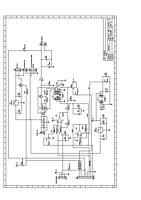
This is a schematic of the controller. The heart of the controller is U1, a LM78S40 PWM control IC. I had a tube full of these things, so it seemed an obvious choice. The output of U1 drives a TIP34 power transistor which is switched on and off at about 20KHz with a variable pulse width. The gain of the TIP34 is pretty low, so in a future version, I would use a hefty P-channel power MOSFET. The chopped voltage is filtered by L1 and C2 to give a variable DC voltage to the TEC Module connected to J4. The comparator in the 78S40 is driven by an error voltage developed by U5A, which is 1/2 of a TL082 dual op-amp. The error voltage is 10 times the difference between the setpoint and the actual temperature. The temperature sensor is an LM35DT, which outputs 20mV per degree C. The pull-down resistor to -5V allows it to work at negative temperatures. If you want to use this circuit with a heater instead of a cooler, just swap the temperature sense voltage and the setpoint voltage inputs to R6 and R7 The ability to work around zero degrees C added some complexity to the circuit in the form of U7, which generates a -5 volt supply, and U5B, which gives us a negative voltage reference. If you only want to control the temperature to positive values, you could drop both of these parts, and use the internal op-amp in the 78S40, wired just like U5A J5 allows a connection to a microprocessor or other external controller to give remote control and monitoring of the temperature controller. On this connector one can monitor the temperature, control or monitor the setpoint, turn the cooler or heater completely off, and turn the fan off. Finally, I added U3, J3, and J7 to provide auxilliary outputs for the controller enclosure fan and for the LNA power. This assumes that the whole thing is driven by a 16 to 18 volt power supply. If you use a higher voltage then I would add another regulator for the LNA supply. |
![]()
Last Revised: 8-February-2004