Bryant Labs
Seismic Vault Construction
![]()
Note: Click on each image to see a larger version. In most browsers, you can right click and choose to open it in a separate window.
 |
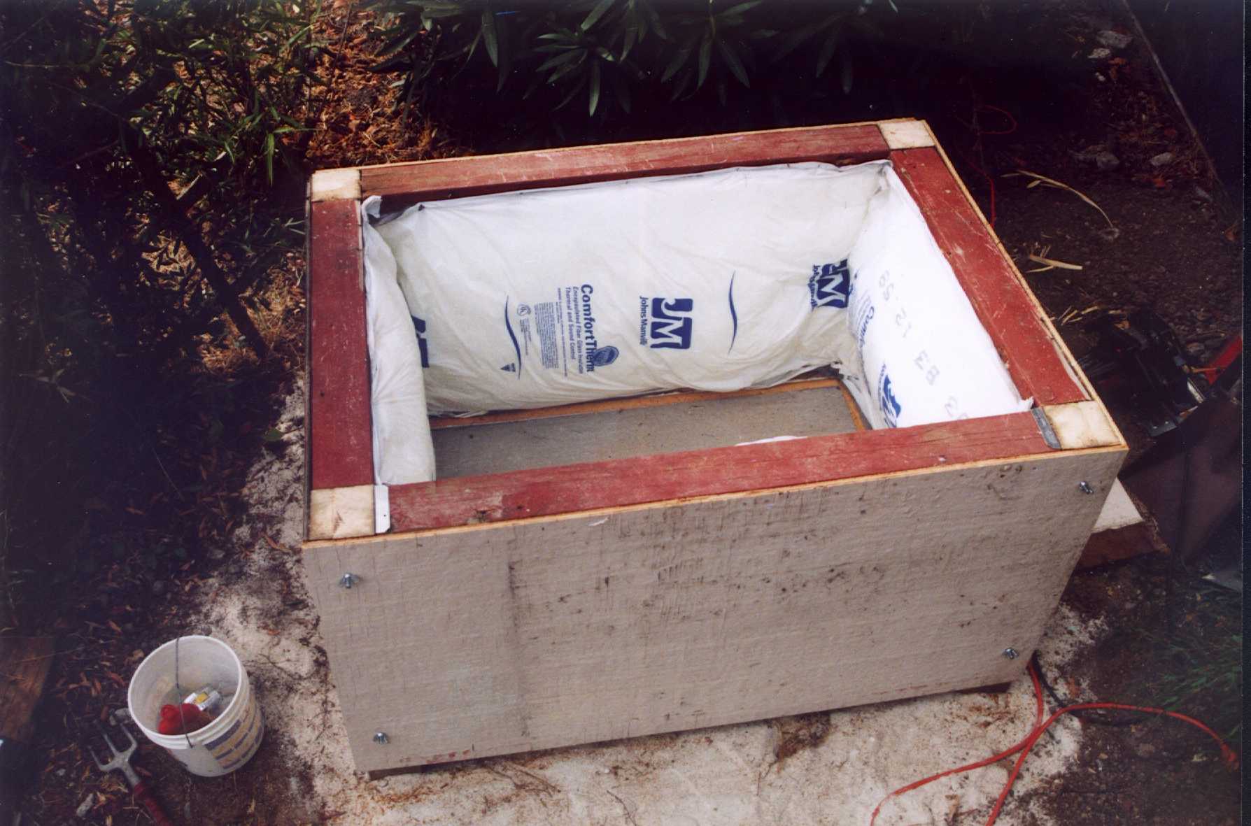
This picture shows the early phase of the construction of my "Seismic Vault". My soil is very heavy clay, hundreds of feet deep, so digging a deep hole to hit bedrock is pointless. My main concern was to maintain good coupling to the soil, but not to the housing. I also wanted to have the vault well insulated to keep the temperature as stable as possible. Despite my best efforts, I had to add a heater to keep the inside temperature within a few degrees. See Below. The slab is between 3 and four inches thick, 2 feet wide by 3 feet long, sitting on relatively undisturbed soil. In the near right corner (under the plastic bag) are the ends of some conduit. One carries power in, and the other is for the signals back to the lab. The slab is surrounded by 1 inch thick foam insulation board about 8 inches wide, set in a narrow trench around the slab. Separate from the slab are the four 4x4 posts, each about 3 feet long. They are joined by two rings of 2x4's, the bottom ones are treated. The top ones are recycled from a fence I tore down. The front pair are sitting in metal brackets, but are not permanently attached to the posts. |
 |
In this next picture, the side panels and wall insulation are installed. Here you can see the four wing nuts that hold the front wall on. The front wall panel is nailed to the cross members to form a complete unit with insulation. The wing nuts are threaded onto "hanger bolts" which have a coarse thread, like a lag screw, on one end, and a fine thread, like a machine screw, on the other. These happen to be 5/16 inch. |
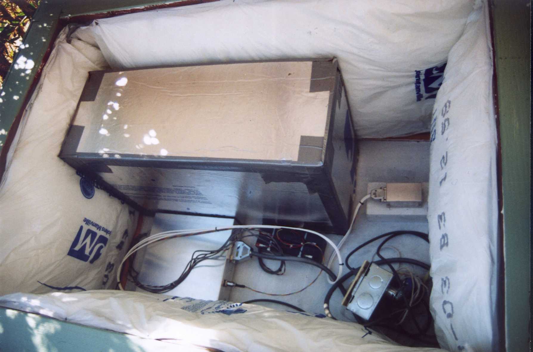 |
This picture shows the inside of the complete vault with the seismometers installed. My Vbb is under the foam box in the upper (back) left corner, and the 3-axis accelerometers are in the little metal box attached to the brick in the right corner. Both seismometers are bolted to the slab in case we get a really big jolt. In front of the Vbb is the signal conditioning box and the backup batteries. |
 |
Finally, here's what the whole thing looks like with the lid closed and a nice coat of paint all over it. The lid is hinged for easy access, and it is insulated. It's really nice to be able to open the top and take off the front, especially when working on the Vbb, which has a very heavy base of concrete. |
|
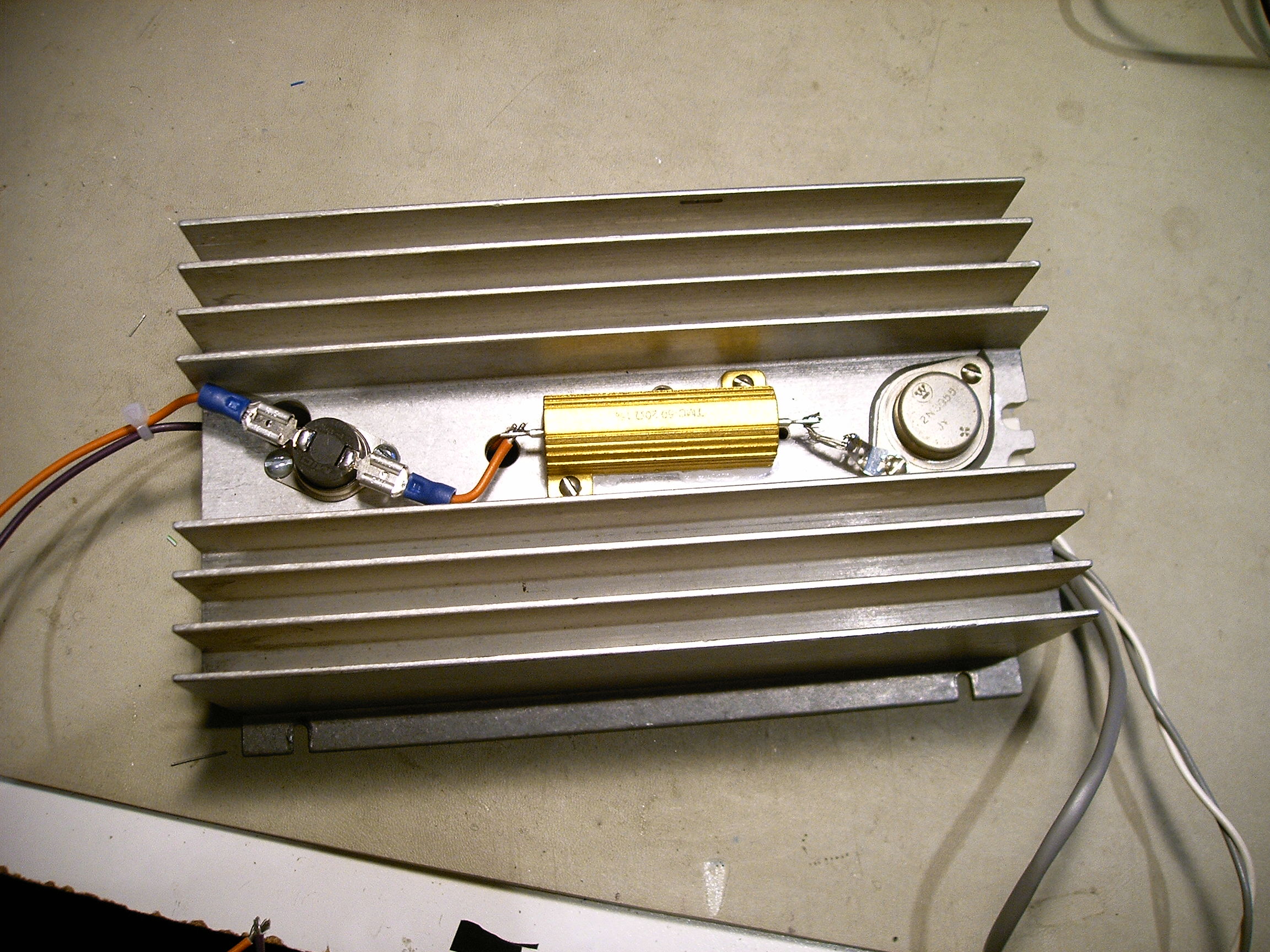
Simple insulation can't keep the inside temperature even when the outside temperature here in Santa Rosa goes from 50 F in the morning to over 90F in the afternoon. I finally decided to add a linearly controlled heater. I had a really big heat sink with a 2N3055 mounted to it, so I added a 20 ohm 50 watt resistor as the heater. It turns out that by putting them together on the same heatsink, the power output is linear with the current into the base. The other object on the front is a thermal cutout, to guard against some failure. It kills power to the heater if the heatsink temperature gets above 75C. |
|
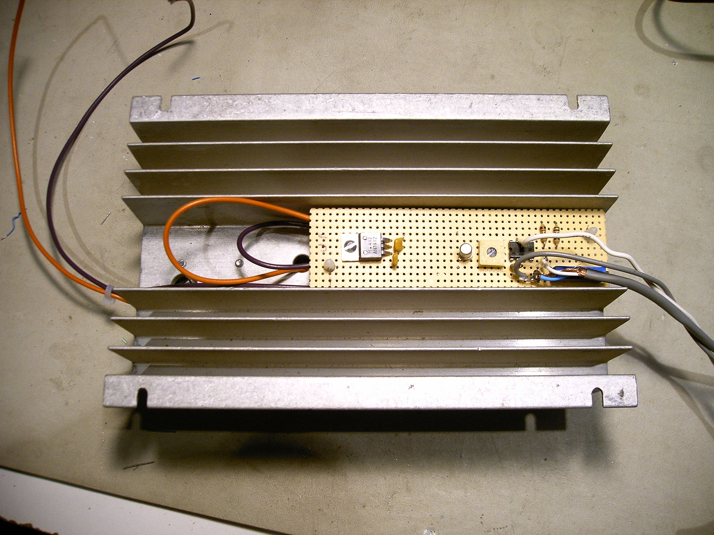
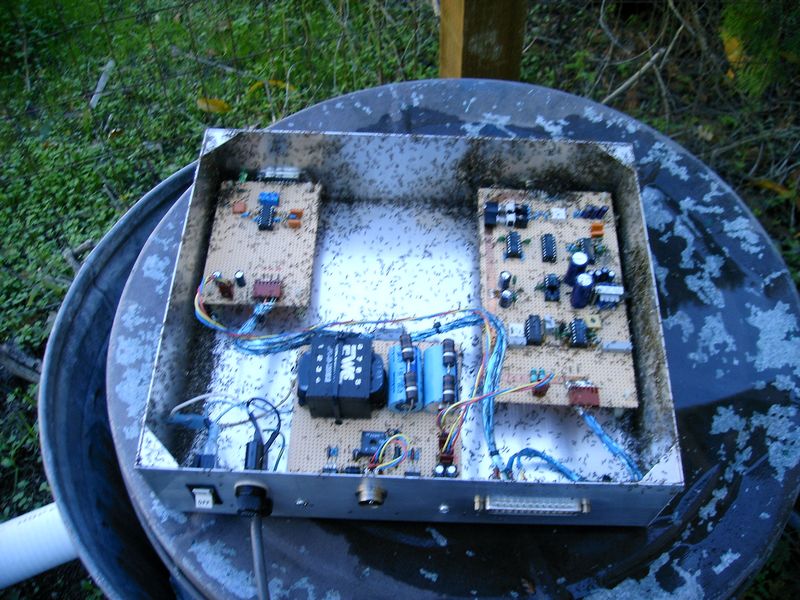
Here's a shot of the back of the heatsink. I mounted the control circuit on a narrow piece of perfboard behind the power transistor. |
|
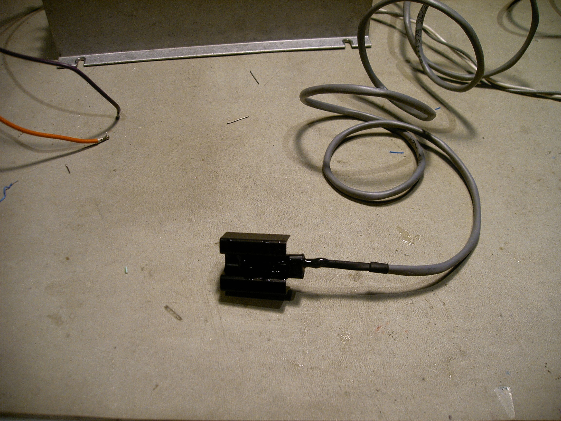
This is the temperature sensor. It's a basic bead style thermistor with a nominal 10K resistance at 25C, and a negative temperature coefficient. To improve the coupling to the air in the vault, I epoxied it to a small heatsink. |
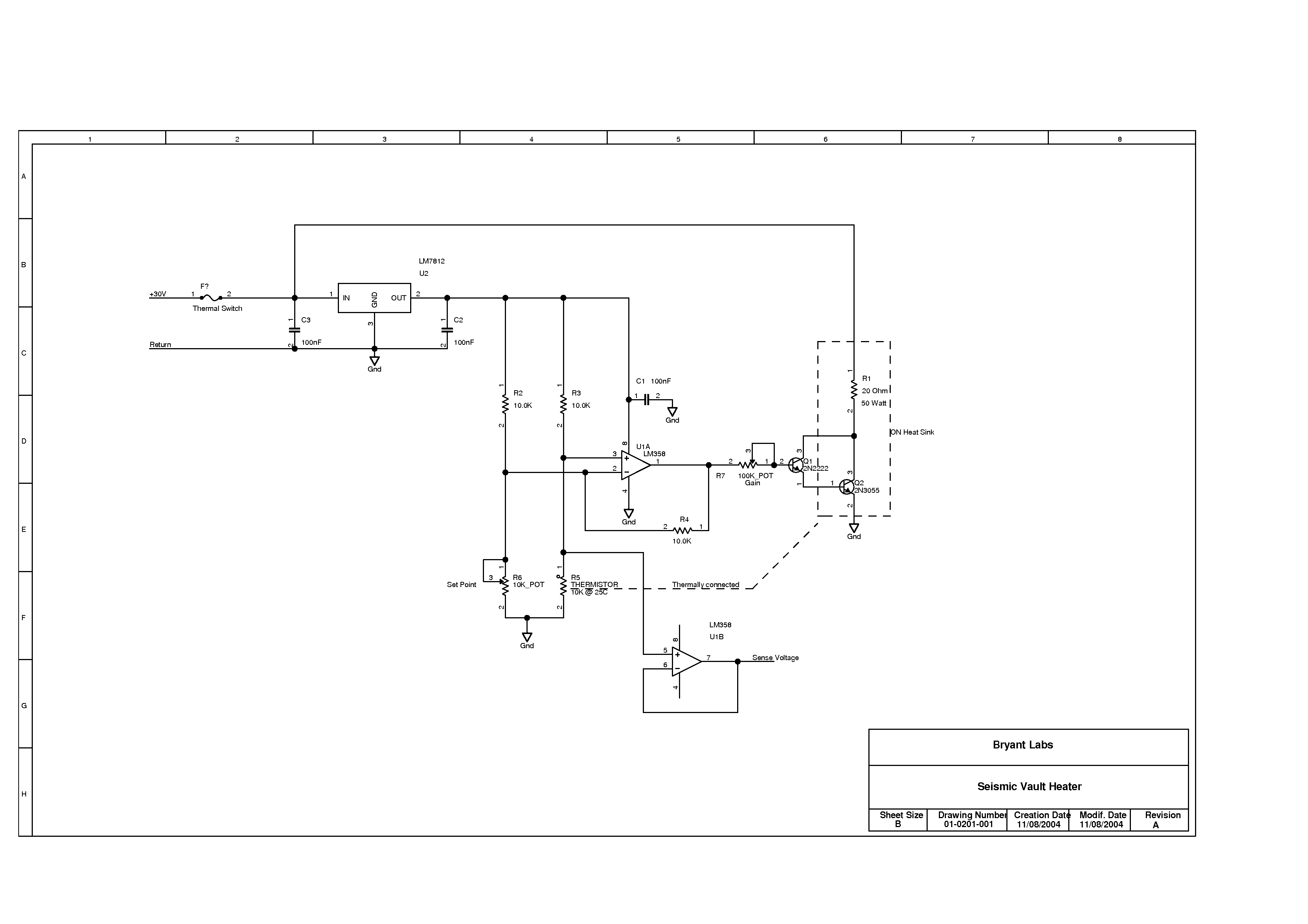
Click on the image above for a GIF file of the schematic. If you prefer, you can also view the schematic as a PDF file |
Finally, here's the schematic. It all starts with a bridge connection of the sensor, balanced by a pot. Set the pot value to be equal to the thermistor at the temperature desired. The difference is amplified by U1, a basic LM358. The gain of this stage is only 2 because there is plenty of gain in the tranistors. I use the other half of the LM358 to buffer the temperature sensor voltage for remote monitoring. The output of the difference amplifier drives the base of Q1, a 2N2222 which is connected to Q2, the 2N3055, in a Darlington configuration. Together, the two transistors have a gain of between 2,000 and 20,000 depending on the parts. That's why there is a "Gain" adjustment pot. When setting up the heater, turn it on, and while the sensor is still cold, adjust the pot so Q2 is just at the edge of saturation. With a volume like my vault, the air temperature stays within a few tenths of a degree C. It's important not to try controlling the temperature inside the actual Vbb enclosure. A heater like this would just set up some nasty air convection currents which would make the Vbb sensor move all over the place. Power comes from a simple Transformer/Rectifier/Capacitor based power supply |
|
During the weeks just before installation of the heater, I noticed that the signals from the instruments in the vault were getting erratic. I chalked it up to a noisy connector, and figured I would fix it when I installed the heater. Instead, I got a creepy surprise! What I intended as a seismometer had turned into an ant farm. Apparently the nice warm electronics box seemed like heaven to these ants. I had to tear down the whole thing to clean it, and even had to replace one of the connectors on the VBB board. The metal electronics box had a couple of extra holes in it because of design changes along the way. You can be sure they have been sealed up! I've also put some ant traps in the vault, with a reminder in my calendar to replace them in three months. |
![]()
Last Revised: 3-December-2004