Bryant Labs
Radio Astronomy and SETI
![]()
Below are some details of my Radio Astronomy Receiver. First, a block diagram:
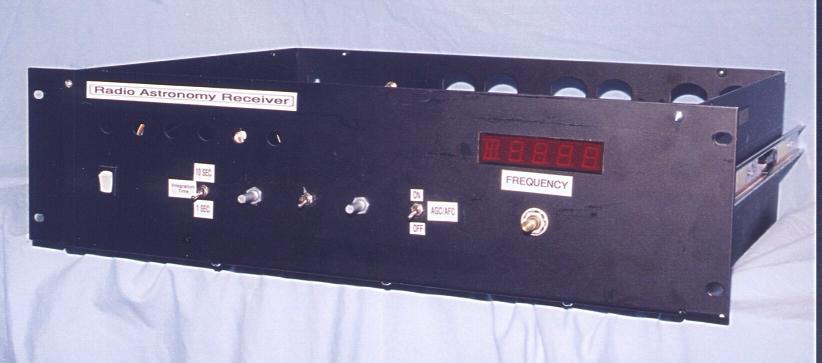
Here is a picture of the front panel. On the right is the frequency display,
with the control knob below it. I used a rotary encoder to change the frequency in
50Khz Steps. The other knobs and switches, from left to right, are:
Power On/Off; Integrator time constant (1 or 10 seconds); Speaker Volume;
AM/FM (for the speaker); spare; and AGC&AFC ON/OFF.
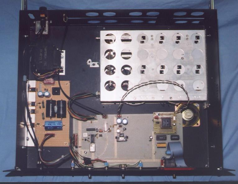
And here's a shot of the inside, from the top. Down the left side is the power supply, starting with a transformer in the back, and a voltage regulator board toward the front. I used linear regulators which are heatsinked to the side wall of the box via a piece of aluminum angle. In the back right is the military surplus sonobuoy receiver which I modified to be synthesizer controlled over a range of 135MHz to 150 MHz. Don't try this at home... Finally, in the front right is the control board. It holds a 68HC11 processor module which controls the synthesizer chip and drives the display. This board also holds the analog processing circuits and the speaker amp.
From this photo, you can also see a construction trick I use. In order to get decent grounding in a circuit built on perfboard, I use copper foil tape which is commonly used for Stained Glass. You can find it in most craft stores. It is 1/4 inch wide and sticky on the back. It is tempting to ring the outside of the board with this, but don't do it: You will just create a "Ground Loop" and cause more noise. The best way to minimize noise is to pick a spot on the board and create a Single Point Ground. In this case, it is near the power supply connector on the left. Each circuit or related group of parts should have it's own strip of tape back to that point. The Single Point Ground is also where my bulk decoupling caps (100uF or so) are located.
Last Revised: 16-June-2003