SARA Western Conference 

I just got around to uploading my pictures from the SARA Western Conference held at Stanford University last weekend. I had a great time, and I'm sure everyone who attended did too. Bill and Melinda Lord did a fantastic job organizing the meeting, and a special thanks goes to Phillip and Deborah Scherrer who were our hosts at Stanford.


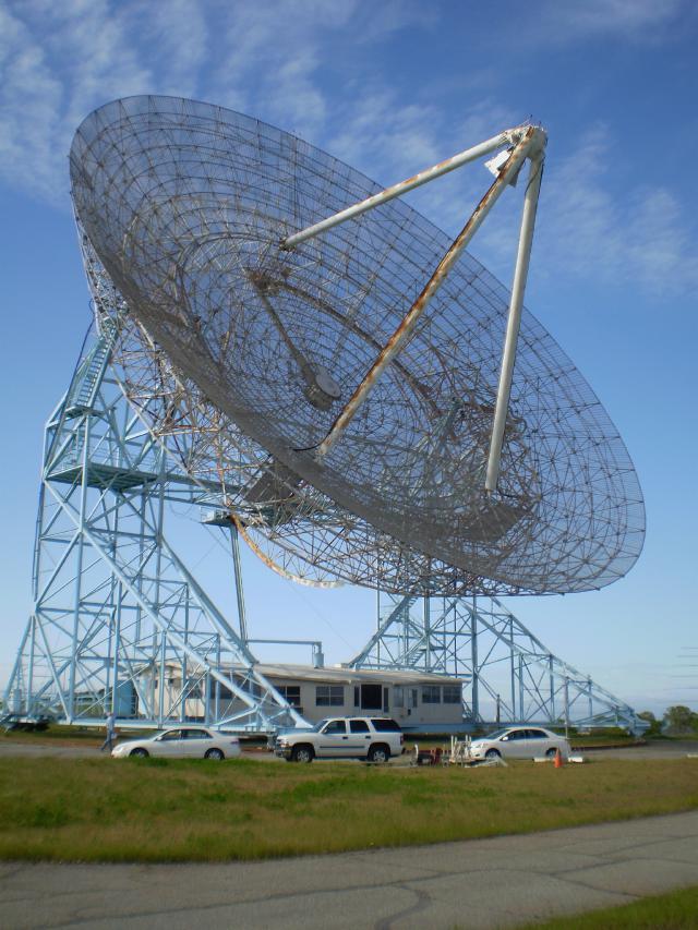
This is the famous Stanford Dish from the front side. After spending most of the conference indoors, it was nice to get out and have a look about. Our first stop was the big dish to get a detailed inside tour. The dish is 150 feet in diameter - you get some sense of scale from the cars in front of it. The whole works including the control room rotates around on four rail car wheels riding on a circular track.

It was a beautiful day, and we could see Mount Hamilton, Mount Diablo, and NASA Ames research center:


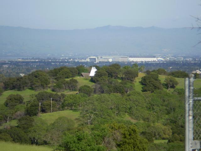
I think the rectangular structure in the picture is the inlet to the huge wind tunnel at Ames. In the foreground, the interesting shaped white building is the Wilcox Solar Observatory which we toured after visiting Stanford Radio Club facility. All of these facilities are within a huge park-like area open to hikers. We felt bad riding in cars while they trudged up the hills!

That's it for now, I'll comment on some of the presentations next time.

Cheers,

Keith

[ add comment ] ( 59 views ) [ 0 trackbacks ] permalink related link ( 3 / 1891 )
Solar Monitor Chassis Progress 


I've completed most of the mechanical work on the Solar Monitor Chassis. This picture shows the front panel with the core module interface on the left and four completed bar graph modules installed. The upper left control is a lighted push-button switch with an integral yellow LED. It lights if one of the modules lit the red LED. Pushing the button clears that latch. To the right of that is the beeper volume. Below the push-button switch is an indicator that is green if Radio Sky Pipe is actively scanning channels. It goes red if something stops.

The layout isn't aesthetically ideal because I recycled the panel and had to work around holes that already existed. The good news is that the array of holes for the speaker were already done and I had a speaker that fit them.


This shows some of the guts of the thing. On the left you can see the connections to from the modules to the core module. The right side is all power supply. The box in the rear holds the power entry module and acts as a junction box for the AC. In front of that is the 5V/3A supply for the LEDs and digital stuff. Just visible in the front corner is the 18VCT transformer that supplies the OP-Amps and A/D converter.

I fired it up with Sky Pipe and it works great so far. Now I need to get the front end radios working.

Cheers,

KeithP
[ add comment ] ( 12 views ) [ 0 trackbacks ] permalink ( 3 / 1837 )
Striking Sparks 

Last night was the annual Striking Sparks Awardsgiven by the Sonoma County Astronomical Society (SCAS). This phenomenal program has awarded more than 230 telescopes to promising young scientists in Sonoma County California. This is the 25th year of this program that was started by Robert Ferguson, Larry McCune, and the other members of the SCAS. Bob Ferguson is gone now, but the Robert Ferguson Observatory was named in his honor.

The ceremony is simple and homey and focused on the kids. They were all beaming. We could barely constrain them as the ceremony ended and we took them out to the parking lot to have a look at the night sky. We lucked out and it was nicely clear. Orion was ideally situated and was the first target for most of them.

I left feeling warm all over despite the chill in the air. Here were six kids who weren't as shallow and stupid as most you encounter every day. Maybe there is some hope. <Curmudgeon mode off>

Cheers,

Keith
[ add comment ] ( 18 views ) [ 0 trackbacks ] permalink ( 3 / 1812 )
Solar Monitor Module Tests 


I finished work on the Core module, so it's time to put a few things together to see if they work as planned. Here you can see the Core module and a Bar Graph board wired together along with a speaker and the transformer. All the functions work as intended, although I decided to make a simplification of the parallel port activity detector. I had two one-shots wired in series, but I decided that was over complicated. It works just fine with just one that times out if the CS- signal stays inactive too long.

I also made a small change to adapt to the bi-color LED I had on hand. The original design assumed a three leaded type, with a common cathode. The ones in the parts drawer have two leads. The Red and Green die are back-to-back. Easy change since the '4538 one-shot has Q and Q- outputs.

I've been using LM3915's in the Bar Graph boards. Those are the logarithmic scale variant of the LM391x family. I thought it made more sense for the first modules which will be monitoring radio frequencies. Future modules will monitor things like magnetic field strength, so I may go to the LM3914, which has a linear scale.


Here's a shot of the first front panel for the Bar Graph board. I need to tweak the locations of the three holes for the trim-pots, but otherwise I'm really happy with the results. I did a layout in Visio, printed it out, and stuck it to the blank metal part with spray glue. Very carefully center punched the hole locations, and drilled away. My printer had to be set to 101% to get the most accurate output for this. Always check the printed page carefully before cutting/drilling from it.

I still need to decide how to label each panel. I want to have some text that tells me what's being monitored. I may try the decal sheets I bought from Micro-Mark. They look pretty good over simple brushed aluminum.

Next up, I'll do the rack panel work to hold all this stuff.

Cheers,

Keith
[ add comment ] ( 7 views ) [ 0 trackbacks ] permalink ( 3 / 1759 )
Solar Monitor Core Module 


This is the core of the Solar Monitor project. There is a schematic here. This board holds the A/D converter which takes the signals from up to 8 bar graph/amp boards to be digitized and logged by Radio Sky. It also does the power distribution and some other house keeping functions.

In the upper left is the power input. An 18V Center tapped transformer from Jameco connects to the 3 pin molex. That gets turned into +- 10 or so volts DC, which is then regulated down to +- 8VDC by a 7805/7905 regulator pair. You can just about see them mounted to the heat sink - another part scavenged from a dead PC power supply.

Just below the transformer connector is another input from a 5V/3A switching supply from Jameco that supplies the logic and LED power.

The row of smaller molex connectors in the center is for the distribution of power to each of the bar graph boards (BGBs). Next to them are the 8 RCA jacks for the signals from the BGBs. Each BGB does a precision rectification, gain, and offset of the raw audio coming into it.

Finally on the far right is the socket for the MAX186 and the connector to the host computer.

In the lower left corner there is a 74HCT132 quad nand gate that handles the alarm function. Each BGB has an option to drive an open collector alarm bus when the top-most LED is lit. This gate latches that signal and generates a beep.

Next to the '132 is a 74HCT4538 dual one-shot. It's configured to time out if there's no activity on the A/D chip select for more than a second. It has a red/green LED attached so I can tell at a glance if the computer has stopped getting data from the A/D.

In the schematic, the LEDs, Speaker, etc are shown as being on the board for clarity. Next to each one is a tag showing which pin on the 10-pin molex connector it actually goes to.

This still needs some testing, and then it's time for the mechanical work to put the card cage together.

Cheers,
[ add comment ] ( 15 views ) [ 0 trackbacks ] permalink ( 3 / 1903 )

<<First <Back | 1 | 2 | 3 | 4 | 5 | 6 | Next> Last>>