Figuring out how to make the antenna track the sun was fun and interesting. I started out with a book called "Sundials: Their Theory and Construction" by Albert E. Waugh (ISBN: 0-486-22947-5). It takes you through the basics of how the sun appears to move through the sky. Remember that it's the Earth that's rotating... In the appendix of the book are several helpful tables of data. I ended up using some of that data in the PIC firmware.
The key to all of this is something called The Equation of Time (EOT), which describes how the position of the sun at noon varies throughout the year. From that equation, one can calculate the Solar Azimuth Angle and the Solar Elevation Angle.
The problem is that both require calculations of sin, cos, tan, and their inverse functions. I'm trying to do this in a relative small PIC processor. The only way to get there is to figure out how much precision I really need.
One Aside: I know I could run some planetarium software on my PC and just send standardized messages to the antenna driver to move it. That would be fine if I was willing to always have the application running on my desktop. I like to build stuff that requires less direct control by my PC. In this case, I want the antenna system to track the sun by itself, with higher level status and control to/from the PC.
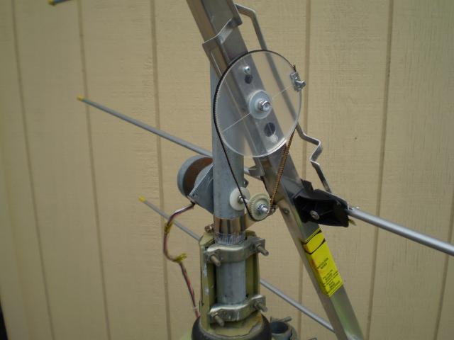
Anyway, the half power beamwidth of the HD-6000 at 108 MHz is about 70 degrees, so that gives a fair amount of leeway in Azimuth. I don't have any data for the vertical beamwidth, but I decided that 5 degree steps in each direction should be fine. I worked from there and decided that I needed to move the antenna every 20 minutes to keep it reasonably well aimed at the sun.
To do all of this with integer math, I decided to scale the trig functions by 1000: 0-0.999 becomes a three digit integer from 0-999. To conserve memory, I have one table that converts integer angles from 0 to 90 degrees into the sin times 1000: sin(45) = 707. From this one table, I calculate the sin of any angle by inverting the angle and/or result. I use similar tricks to get the cos of any angle. The tricky bit is figuring out when you need to divide by 1000 to stay in scale.
Here's how it ends up working in the software.
Get the time from the RS-485 port. See my Precise Time and Frequency Page for details of where that comes from. Convert it from UTC to Local Mean Solar Time(LMST) which corrects for the difference between solar time and my exact longitude, and adjust it for today's equation of time. The EOT correction is done every morning at 2:30 AM.
Every 20 minutes, calculate a new position for the antenna:
Look up today's solar declination angle
Calculate the hour angle from the LMST
Calculate the Solar Elevation using the trig functions
Calculate the Solar Azimuth using the trig functions
If the sun is above the horizon, move both motors.
I have one place where I need to fudge to make up for the limitations of the integer math. When the hour angle is zero, right at noon LMST, the azimuth equation really needs more digits of precision to avoid bad results. I just check for the angle = zero and set the azimuth to zero. Much simpler than dealing with bigger variables throughout.
The code uses about half the available ROM and RAM. That leaves room for future improvements, but I'm really sure I couldn't have fit the floating point and trig routines from the C compiler.
It's working well, and most of the tweaks I've made have more to do with finding home and dealing with the limit sensors.
Drop me a line if you want to see the actual code.
Cheers,
Keith
[ add comment ] ( 11 views ) [ 0 trackbacks ] permalink The key to all of this is something called The Equation of Time (EOT), which describes how the position of the sun at noon varies throughout the year. From that equation, one can calculate the Solar Azimuth Angle and the Solar Elevation Angle.
The problem is that both require calculations of sin, cos, tan, and their inverse functions. I'm trying to do this in a relative small PIC processor. The only way to get there is to figure out how much precision I really need.
One Aside: I know I could run some planetarium software on my PC and just send standardized messages to the antenna driver to move it. That would be fine if I was willing to always have the application running on my desktop. I like to build stuff that requires less direct control by my PC. In this case, I want the antenna system to track the sun by itself, with higher level status and control to/from the PC.
Anyway, the half power beamwidth of the HD-6000 at 108 MHz is about 70 degrees, so that gives a fair amount of leeway in Azimuth. I don't have any data for the vertical beamwidth, but I decided that 5 degree steps in each direction should be fine. I worked from there and decided that I needed to move the antenna every 20 minutes to keep it reasonably well aimed at the sun.
To do all of this with integer math, I decided to scale the trig functions by 1000: 0-0.999 becomes a three digit integer from 0-999. To conserve memory, I have one table that converts integer angles from 0 to 90 degrees into the sin times 1000: sin(45) = 707. From this one table, I calculate the sin of any angle by inverting the angle and/or result. I use similar tricks to get the cos of any angle. The tricky bit is figuring out when you need to divide by 1000 to stay in scale.
Here's how it ends up working in the software.
Get the time from the RS-485 port. See my Precise Time and Frequency Page for details of where that comes from. Convert it from UTC to Local Mean Solar Time(LMST) which corrects for the difference between solar time and my exact longitude, and adjust it for today's equation of time. The EOT correction is done every morning at 2:30 AM.
Every 20 minutes, calculate a new position for the antenna:
Look up today's solar declination angle
Calculate the hour angle from the LMST
Calculate the Solar Elevation using the trig functions
Calculate the Solar Azimuth using the trig functions
If the sun is above the horizon, move both motors.
I have one place where I need to fudge to make up for the limitations of the integer math. When the hour angle is zero, right at noon LMST, the azimuth equation really needs more digits of precision to avoid bad results. I just check for the angle = zero and set the azimuth to zero. Much simpler than dealing with bigger variables throughout.
The code uses about half the available ROM and RAM. That leaves room for future improvements, but I'm really sure I couldn't have fit the floating point and trig routines from the C compiler.
It's working well, and most of the tweaks I've made have more to do with finding home and dealing with the limit sensors.
Drop me a line if you want to see the actual code.
Cheers,
Keith

 ( 3 / 2023 )

 Calendar


